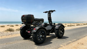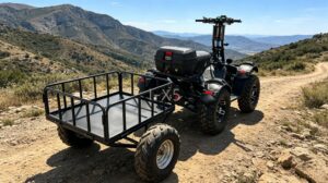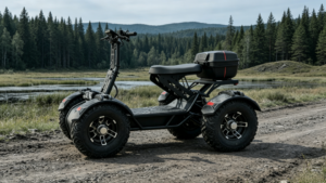
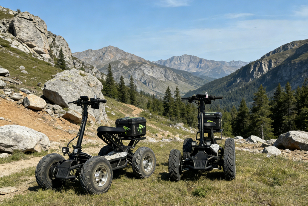
Welcome to the world of electric off-road adventure! The Edge Scooter iX5 is a powerful electric ATV scooter that combines rugged performance with eco-friendly technology. This comprehensive guide will walk you through every step of assembling and setting up your new vehicle, ensuring you get the most out of your investment while staying safe.
1. Understanding Your iX5 Electric ATV Scooter
Before diving into assembly, let’s appreciate what makes the iX5 special. This electric all-terrain vehicle features a robust 60V battery system, a powerful motor capable of handling various terrains, and innovative features like 4WD/2WD switching capability. With a net weight of 205 kg (approximately 452 lbs), this is a substantial machine that demands proper assembly and respect.
2. Unboxing and Inspection
2.1 Checking Your Shipment
When your iX5 arrives, the first step is critical: inspect the packaging. Look for:
- Visible damage, dents, or deformation on the outer box
- Water stains or signs of moisture exposure
- Any unusual sounds when gently moving the box
Pro tip: Take photos immediately if you notice any damage. This documentation will be invaluable if you need to file a shipping claim or contact customer support.
2.2 Parts Checklist
Carefully open the box and verify all components are present. Here’s your complete checklist:
| Item | Component | Quantity | Notes |
|---|---|---|---|
| 1 | iX5 Main Frame Assembly | 1 | Includes frame, motor, and battery compartment |
| 2 | Handlebar Riser Pole | 1 | With height adjustment mechanism |
| 3 | Seat Assembly | 1 | Quick-release base included |
| 4 | Rear Storage Trunk | 1 | May be pre-installed or require assembly |
| 5 | Battery Pack | 1 | May be pre-installed or require installation |
| 6 | Battery Charger | 1 | 60V factory charger |
| 7 | User Manual | 1 | This guide |
| 8 | Key Set | 1 | Power ignition keys |
| 9 | Certificate of Conformity/Warranty Card | 1 | Keep in a safe place |
| 10 | Front/Rear Tool Baskets (Optional) | 1–2 | If ordered |
| 11 | Trailer Coupling (Optional) | 1 | For towing package orders |
IMPORTANT: If any component is missing or appears damaged, stop immediately and contact your dealer. Never attempt to assemble or use the vehicle with damaged or missing parts.
3. Setting Up Your Assembly Workspace
Creating the right environment makes assembly safer and more efficient:
| Requirement | Specification |
|---|---|
| Workspace | Flat, dry, well-ventilated indoor area (minimum 10 m² / 108 ft²) |
| Flooring | Hard, level surface (concrete or rubber mat) – avoid carpet or soft ground |
| Lighting | Bright, clear illumination for seeing small parts and fasteners |
| Tools | Besides included tools, prepare: torque wrench, adjustable wrench, spirit level |
| Helpers | 2-person team recommended (vehicle weighs 205 kg/452 lbs) |
| Time | Allow 1.5–2 hours for complete assembly and setup |
Why these matter: The iX5 is heavy and precise. A proper workspace prevents accidents and ensures your scooter is assembled correctly the first time.
4. Step-by-Step Assembly Instructions
Step 1: Installing the Handlebar Riser Pole (Steering Column)
WARNING: The riser pole is the core steering component. Improper installation can cause steering failure and serious injury.
| Step | Action | Key Detail |
|---|---|---|
| 1 | Place main frame on level ground | Ensure all four wheels touch the floor |
| 2 | Inspect riser pole bottom flange | Should align with frame steering head |
| 3 | Insert riser into frame headset | Align locating pin with groove – listen for “click” |
| 4 | Tighten riser bolts (4 M8 bolts) | Use diagonal pattern, gradually tighten |
| 5 | Check vertical alignment | Use spirit level to ensure no tilt |
| 6 | Apply final torque | 25–30 N·m – don’t overtighten |
TIP: The riser pole height is adjustable. Loosen the quick-release lever on the side, adjust to your height (while seated on the vehicle), then re-tighten securely.
Step 2: Installing the Handlebar and Controls
| Step | Action | Important Notes |
|---|---|---|
| 1 | Insert handlebar into riser top clamp | Ensure symmetrical positioning |
| 2 | Adjust handlebar angle | Simulate riding position – brake levers and throttle should feel natural |
| 3 | Tighten clamp bolts (2 M6 bolts) | Torque: 15–20 N·m |
| 4 | Check brake lever travel | Should move smoothly and return with spring force |
| 5 | Test throttle rotation | Must rotate freely and return to zero position automatically – no sticking allowed |
| 6 | Connect electrical harnesses (if shipped separately) | Align connectors, listen for “click” to confirm lock |
NOTE: All electrical connectors are waterproof. Ensure rubber seals are intact – never force connections.
Step 3: Installing the Seat Assembly
| Step | Action | Description |
|---|---|---|
| 1 | Inspect seat quick-release mechanism | Should open/close smoothly when pressed |
| 2 | Align seat base with rear frame mount | Guide slots must align with frame rails |
| 3 | Push seat forward until “click” | Lift test – confirm lock is secure |
| 4 | Test quick-release function | Press button, pull seat back – should release cleanly |
Stand-up Riding Mode: To switch to stand-up mode, press the quick-release button and slide the seat backward to remove it. Ensure the foot platform grip tape is intact when riding standing up.
Step 4: Installing the Rear Storage Trunk
| Step | Action | Detail |
|---|---|---|
| 1 | Align trunk base with rear mounting plate | Pre-drilled holes should match frame holes |
| 2 | Secure with bolts (4 M6 bolts) | Torque: 10–12 N·m |
| 3 | Test lid opening/closing | Should operate smoothly with secure latch |
| 4 | Check maximum load | ≤ 15 kg (33 lbs) – exceeding may affect center of gravity |
Step 5: Installing the Battery Pack (If Not Pre-Installed)
DANGER: The battery is high-voltage (60V). Keep hands dry and remove all metal jewelry before handling.
| Step | Action | Critical Safety Note |
|---|---|---|
| 1 | Open battery compartment with key | Inspect for foreign objects or moisture |
| 2 | Check battery externally | No deformation, leakage, or odors – stop if damaged |
| 3 | Lift battery (2-person lift, 25–35 kg) | Pay attention to carry handle orientation for future removal |
| 4 | Slide into compartment | Align with bottom rails, push fully until “click” locks it |
| 5 | Connect main power plug (Anderson or aviation connector) | Match polarity: Red (+), Black (-) |
| 6 | Close and lock compartment | Ensure water seal is properly engaged |
Battery Removal: For long-term storage or indoor charging, open the compartment, disconnect the power plug, lift the carry handle, and slide the battery backward to remove.
Step 6: Installing and Checking Tires (If Applicable)
Note: Standard shipments come with tires pre-installed and inflated. If not, follow these steps:
| Step | Action | Key Detail |
|---|---|---|
| 1 | Mount tire onto rim using tire irons | Check directional arrows or “OUTSIDE” markings |
| 2 | Install valve stem and inflate | Standard pressure: 15–20 psi (check sidewall label) |
| 3 | Check bead seating | Use soapy water to test for air leaks |
| 4 | Install hub caps (if equipped) | Press into position until clips engage |
Step 7: Installing Reflectors and Safety Markings
| Step | Action | Note |
|---|---|---|
| 1 | Clean mounting surfaces (fenders, side panels) | Remove grease and dirt for better adhesion |
| 2 | Apply reflectors per local regulations | Enhances nighttime visibility |
| 3 | Apply Edge Scooter branding decals | Smooth out air bubbles for professional finish |
5. First-Time Charging
Before your maiden ride, complete the initial charge:
| Step | Action | Important Detail |
|---|---|---|
| 1 | Confirm battery is correctly installed and power switch is OFF | |
| 2 | Connect charger output to vehicle charging port | Align connectors until “click” |
| 3 | Plug charger into standard AC outlet (220V/110V per region) | Ensure grounded outlet |
| 4 | Observe charger indicators: Red = Charging, Green = Full | First charge: 10 hours recommended |
| 5 | After charging: Disconnect AC first, then vehicle plug | Prevents arcing damage |
TIP: Fully charging to 100% on first use calibrates the Battery Management System (BMS) for accurate range predictions.
6. Setup and Calibration
6.1 Instrument Panel Check
| Item | Method | Pass Criteria |
|---|---|---|
| Power-on Self Test | Insert key, turn to ON | All LCD segments display, no error codes |
| Battery Indicator | Observe battery icon | Shows percentage matching actual charge level |
| Speed Display | Gentle throttle, observe reading | Within 5% of GPS speed reading |
| Gear Display | Shift D/R/P | Screen shows correct gear |
| Drive Mode | Toggle 4WD/2WD | Screen shows correct mode |
| Lighting | Activate headlight/tail light | Icons appear on display |
| Odometer | Check total distance | New vehicle: 0–5 km (transport test distance) |
6.2 Steering System Calibration
| Check | Method | Pass Standard |
|---|---|---|
| Steering Free Play | Gently wiggle handlebars side-to-side | ≤ 10° of play |
| Self-Centering | Release handlebars while riding | Vehicle tracks straight |
| Steering Damping | Full left to full right turn | No binding, rattling, or excessive looseness |
6.3 Brake System Calibration
| Check | Method | Pass Criteria |
|---|---|---|
| Brake Lever Travel | Squeeze brake lever | 20–30 mm lever-end movement |
| Brake Sensitivity | Light braking at low speed | Smooth deceleration, no skidding |
| Brake Balance | Test front/rear separately | Proper distribution, no pulling to one side |
| Parking Brake | Park on slope in P mode | Vehicle doesn’t roll |
6.4 Suspension System Calibration
| Check | Method | Pass Criteria |
|---|---|---|
| Ride Height | Measure fender-to-ground front and rear | Left/right height difference ≤ 10 mm |
| Damping | Press each corner, release | 1–2 rebound cycles then settle |
| Suspension Noise | Drive over bumps | No metal-to-metal contact sounds |
6.5 Motor and Drivetrain Test
| Check | Method | Pass Criteria |
|---|---|---|
| Motor Operation | Lift wheels, test at idle | Smooth rotation, no vibration or abnormal noise |
| 4WD Switching | Switch while stopped | Smooth engagement, display correct mode |
| Acceleration Response | Apply 50% throttle | Linear response, no hesitation or lurching |
| Reverse Function | Engage R, gentle throttle | ≤ 5 km/h, audible beeper if equipped |
6.6 Lighting System Test
| Check | Method | Pass Criteria |
|---|---|---|
| Headlight | Turn on | All LEDs illuminate, projection ≥ 30 m |
| Tail Light | With headlight on | Red light steady |
| Brake Light | Squeeze brake lever | Tail light intensifies or flashes |
| Turn Signals (if equipped) | Activate left/right | 60–120 flashes per minute |
| Dash Backlight | Dim light or cover sensor | Auto-activates, comfortable brightness |
7. Handlebar Height Adjustment
The iX5 features telescoping handlebars for rider comfort:
Adjustment Steps:
- Loosen the quick-release lever (counter-clockwise rotation)
- Raise or lower handlebar to preferred height while seated
- Lock the lever (clockwise rotation)
- Apply downward pressure on handlebars to confirm secure lock
8. Seat Position Adjustment (If Applicable)
Some iX5 versions offer fore-aft seat adjustment:
| Step | Action |
|---|---|
| 1 | Loosen bolts beneath seat base |
| 2 | Slide seat forward or backward to desired position |
| 3 | Retighten bolts (torque: 15–20 N·m) |
| 4 | Verify seat has no forward/rearward play |
9. Final Assembly Checklist
Before your first ride, confirm every item:
| No. | Inspection Item | Confirmed (✓) |
|---|---|---|
| 1 | All bolts torqued to specifications | |
| 2 | Handlebar riser secure, no wobble or tilt | |
| 3 | Brakes responsive and effective | |
| 4 | Tires at correct pressure | |
| 5 | Battery installed securely, charge ≥ 50% | |
| 6 | Display normal, no error codes | |
| 7 | All lights functional | |
| 8 | Gears shift smoothly (D/R/P) | |
| 9 | 4WD/2WD switching works | |
| 10 | Seat secure (or removed for stand-up mode) | |
| 11 | Storage trunk mounted securely | |
| 12 | Reflectors properly attached | |
| 13 | Tools and spare keys stored safely | |
| 14 | User manual safety section read completely |
10. First Ride Recommendations
| Recommendation | Explanation |
|---|---|
| Choose open space | Flat grass or open dirt, clear of obstacles |
| Start slow | First ride speed: 10–20 km/h (6–12 mph) |
| Test all functions | Acceleration, braking, turning, reverse, 4WD switching |
| Gradually increase speed | Build confidence progressively |
| Wear full safety gear | Helmet, gloves, knee/elbow pads |
| Bring a companion | Experienced rider should accompany first ride |
11. Troubleshooting Common Assembly Issues
| Problem | Possible Cause | Solution |
|---|---|---|
| No display | Battery disconnected / power off | Check connections, key to ON |
| No throttle response | P mode engaged / brake lever stuck | Shift to D, release brake |
| Brake lever too loose | Low brake fluid / air in lines | Bleed brakes or top up fluid – contact dealer |
| Handlebar wobble | Riser bolts loose | Retorque to specification |
| Motor noise | Loose hub bolts / damaged bearing | Check bolts, contact dealer |
| Tire losing air | Loose valve / puncture | Tighten valve, patch or replace |
| 4WD won’t engage | Vehicle not stopped / controller issue | Stop completely, retry; if persists contact dealer |
12. Safety Summary and Maintenance Tips
Remember: The iX5 is a powerful machine. Treat it with respect:
- Always wear appropriate safety gear
- Never ride under the influence of alcohol or drugs
- Check tire pressure before each ride
- Keep battery charged between 20%–80% for daily use
- Store in a dry, temperature-controlled environment
- Perform brake and steering checks monthly
Assembly Complete!
Store this manual with your Electric ATV Scooter documents. Keep all supplied tools and spare keys in a safe, accessible place. Enjoy your iX5 Electric ATV Scooter, and ride responsibly!